
I have been teaching myself some soldering over the last year, to make and augment some musical instruments, and some other, more strange projects. My biggest project by far was this; building a dub siren from scratch. Here I have documented my process and made a guide for anyone who dares to follow in my footsteps.
This dub siren is far from the most simple design. If you want an easy way out, you can find an old birthday card that plays a song or one of those “Mr T in your pocket” gizmos, and just poke’em with a soldering iron and you’re done(like this one). When I started out this project I had no soldering skills at all, but I had some time on my hands and thus I managed to teach myself the basics in a couple of weeks. It was my Christmas holiday, okay? You make it sound like I was unemployed or something.See the full rubdown after the jump.
Breaking news! If you don’t really want your hands wet with all the soldering and hard work, Korg is now releasing their Monotron synth, which does much the same thing as my dub siren, and for the truly nice price of around $85. Product details here. But you don’t want that of course, no, you want to work hard, making your own from scratch! Right? Then read on.
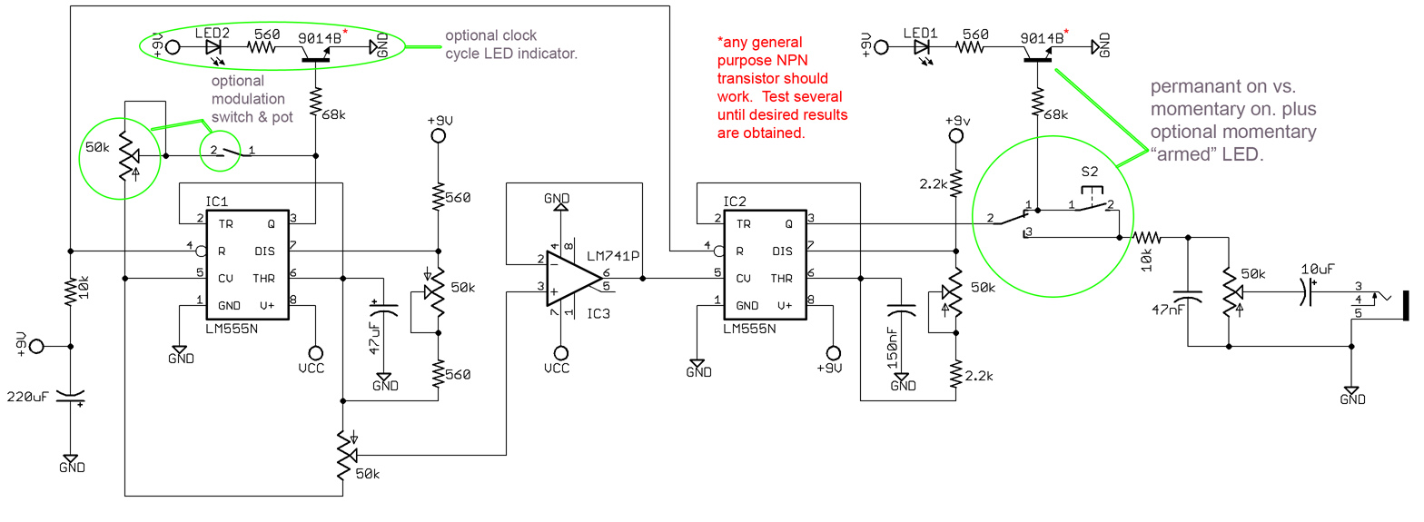
The Dub siren is based around two 555-chips generating the sound. It has buttons for volume, modulation, waveform, phase and frequency. It has a momentary on-button, and also a switch for a «hold» mode. An LED blinks at the waveform rate, and another one to indicate that the hold mode is activated (I skipped that one in my build). Check out the video and schematics at the bottom to see and hear.
Parts needed
IC’s
- LM555n × 2 – I used these, but most 555s will probably do.
- LM741 × 1 – operational amplifier
Pots:
- 50K × 5
Buttons etc.
- off(on) push button × 1 – the momentary on button
- on(on) toggle switch × 1 – permanent on/«hold» switch
- off(on) toggle switch × 2 – modulation on/off switch & power on/off
- LED × 1 – 3mm or 5mm, I used a fiver.
- Either a 9V battery (which will be spent crazy fast), or a 9V wall wart transformer, and a DC socket to plug it in.
- a big TRS socket for the output. You know, like a guitar plug.
- LED holders (for extra finesse and glam)
- IC holders to protect your ICs from overheating when you are soldering. Especially important if your soldering skills are not the best.
- Knobs for the potentiometers
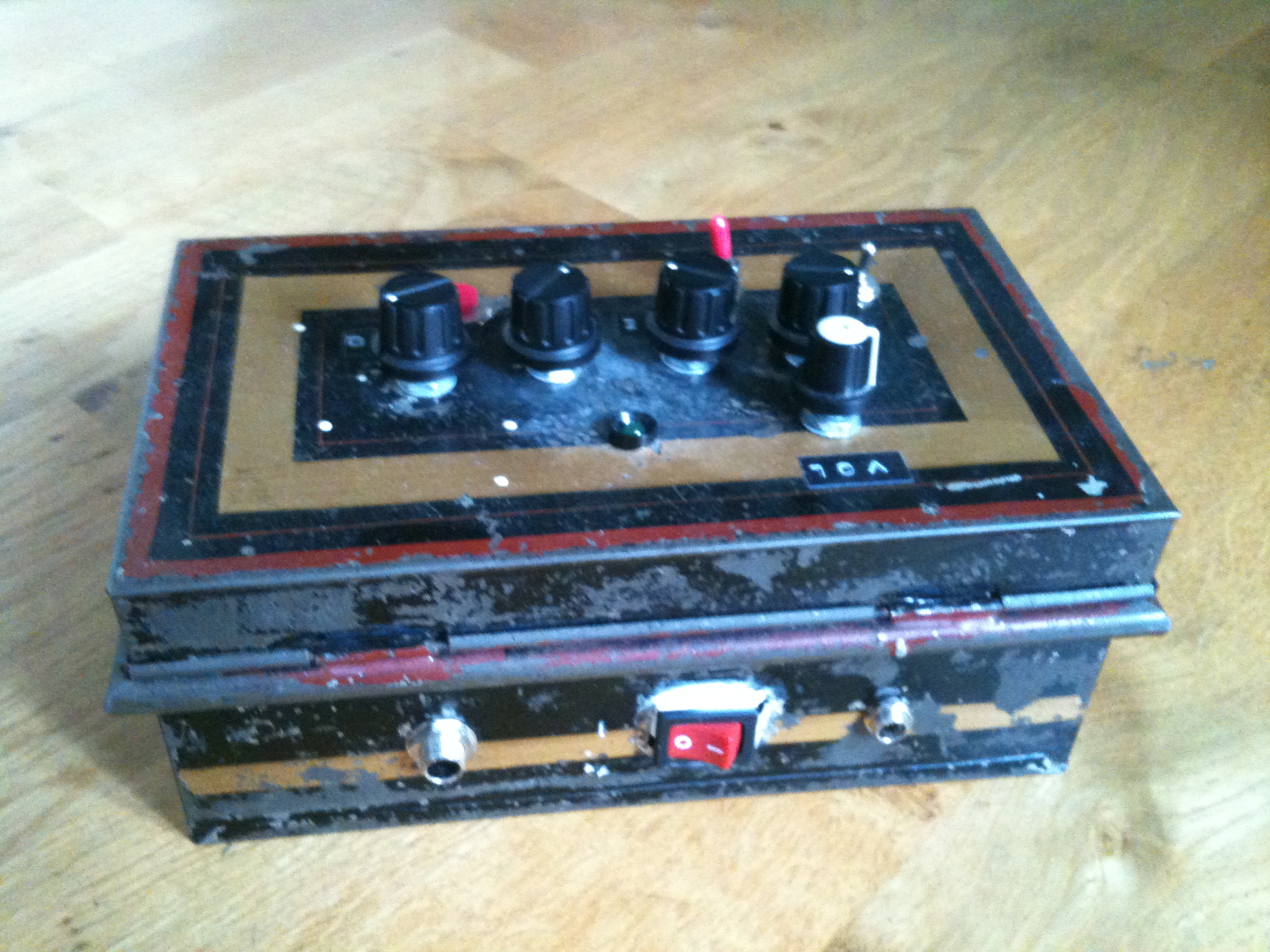
- Some cool casing. I used an old barbers box I found at a flea market.
Capacitors:
- 47μF × 1
- 47nF × 1
- 22μF × 1
- 150nF × 1
- 10μF × 1
Miscellaneous:
- A bunch of resistors. Just buy a packet that has all kinds.
- 2 General purpose NPN transistors (see the circuit diagram below)
If you are Scandinavian and don’t have a store in town that carries the parts, have a look at electrokit.se, where I got (almost) all my parts. Pretty cheap. I later found out Elfa seems to be the industry standard supplier. My experience tells me that buying this stuff online is way cheaper than in a store. And it’s light, so postage is practically free. My 555s I had to order from the UK (totalrobots), so I bought 20 so I’ll never run out.
More things to think about
I actually made this siren twice, the first time around I basically had no idea what I was doing, with the result that if I opened the lid of the siren, or just shook it a little, it would change the sound, or most times just stop working. Hopefully not at a gig. So what to do? Build the whole thing back up from scratch of course!
The second time around I was able to take benefit from everything I had learned from my mistakes. For example, the first version used solid core wiring. Kids, stay away from that stuff! It just breaks all the time. I used it because I was so tired of stripping cables with scissors. Instead, use multi-core wiring and just invest in cable stripper pliers, they are quite cheap.
Secondly, try to make the entire thing on one board, putting all the components as close together as you can. This way you have a way more stable end product, that will not break if you just look at it angrily, like my first one did. As a bonus this makes the whole thing take up less space, enabling you to use a smaller casing. I actually overshot it a bit with my casing, I could easily have gotten away with using something half its size. My tip on this is to wait to decide what to use until after you finished soldering, so you know how much space you need.
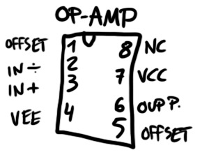
Another thing you need to know about the schematic is; Dave made the IC’s a little confusing. The connection on the top left of your IC does not necessarily correspond with the one on the schematic. I found out what connections are where on the ICs I used (see the pictures above the video). If you use different model IC’s than me you might want to google the model number and go through some PDFs to find it. If you are in doubt, use my drawings to guide you through it.
Another thing is, your line output is going to be huge on this thing. So right before the last output (on the + wire of course), put a resistor, just experiment with different ohms. If not, you might come with the siren to a party, and when some drunken fool rambles up on stage to mash your buttons, he turns the volume all the way up and blows every fuse from here to Calcutta.
According to feedback in the comments, you should tie the 22μF smoothing cap’s negative leg to ground. That way you won’t risk blowing it.
You can nick the original schematic from dave on flickr too. Just keep in mind the alterations I mentioned. If you need to learn how to solder, this article is a good primer.
The schematic is at the bottom of the post, alongside some pictures. Just download that, and see if you can make sense of it. Good luck!
-
- the main circuit
-
- the 555 I used
-
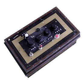
- inside the box (a mess)
-

- tadaa
-
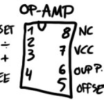
- the op-amp I used
that’s about all I can gather from the schematic. Hope I didn’t forget anything. Just holler in the comments if you have questions, or, you know, comments.
UPDATE: This article has gotten a lot of great comments, so I highly recommend reading through them all, as many of them may answer your own questions.
And if you liked this article, how about showing some love on Facebook? If you “like” my page, I’ll let you know about new projects and things you might like. If you are hard-core (as I know you are), you should enlist for my newsletter! mail-outs are fun, rare and full of free stuff.
[et_bloom_inline optin_id=”optin_4″]


does your schematic include a protection diode or is this something i have to add myself?
Yes it does
I have bought my parts and am just starting to put this together. the chips i have bought are a NE555P for the 555 timer and my op-amp is a lm358n. Will these chips work with the same layout as the schematic? ie which leg is which, and why are the numbers (1-8) on the schematic not in any kind of order?
Lm358 is a dual opamp , instead you need a UA741 wich is a single opamp , They are different .
In schematics pins are not positioned in a precise order , schematics and layout are two different things .
You have to design the layout , based on schematics , wich is a practical disposition of components and traces in space .
If you give me an email I have an easy layout ready to print
Ah, so does this mean I can not use the op amp I purchased? Or can I use it in a different way? Okay my email is ac.dc@live.co.uk
Thanks very much for all your help.
Yes you can use it , but you should adapt the circuit to it , if you don’t know much about opamps its not a good idea . Its better you a find a 741 , it’s the most famous and easy to find opamp , so you can follow the schematics easily.
Hi matey, thanks for the list of parts, is there any kind of tutorial that can be followed. Also, I am stuck with this 9V WALL WART TRANSFORMER, cannot seem to find one. Also, What size/type circuit board would you recommend. Any UK stores other than ‘totalrobots’ which does not exist.
Thanks again,
Chris
What do you mean by VCC in your schematic?
Great job!
Hi Tommy,
VCC means power, basically. Good luck!
Hi, i’m french and I don’t understand all the article but thanks for sharing. I would like to know how is the outpout? is it a jack? Can i, with this schema, have an output like “line”.
Sorry for my english level.
Thank you
Yes Popo, the output for this is a line level “Jack” (1/4″ TRS plug), just like a guitar plug. Good luck!
Hello, I love the sound of your dub siren and would love to own one, are you able to make one for me for a fee? Cheers…
Nope, sorry =)
But as written in the article, you could just buy a Korg Monotron synth for example, they would do the job you need!
/Jacob
Hi Jacob, I really like the sound & controlability of this dub-siren. I’m going to put my own together this weekend.
I’ll let you know how it sounds.
There’s an advanced APC design I stumbled upon recently, you may be interested in as well. The page is in French, but you can right-click in Google Chrome and choose ‘translate’ to change the page to English (if that helps). //modularsynth.wordpress.com/diy-atari-punk-console-stepped-tone-generator-apc-mkii/
Thanks, I’ll check it out!
Hey,
first I wanna say thank you for sharing this project!
But I have some probs with the circut and i don’t know about the negation (circle) on the 555’s at pin 4.
Have you put there a nagation, or without? Could you explain please?
Another thing i wounder, in the part list is written 22μF but in circuit is 220μF. Which is correct?
Greets
D
hi!
im pretty new in this so maybe this is a silly question, but i see that you have connect the dub siren to a stomp box: the output of the siren to the input of the effect, and the output of the effect to the amplifier… is that correct? i always thought thats it has to be to the other way…
(sorry my english and great work!)
bye!
I remade the schematic (for practice and also for later pcb export), the only thing different is the 22µF cap instead of 220µF.
Where should I put the output limiting resistor? And are there other changes that have to be made?
//drive.google.com/open?id=0B196Ckm5zNKhSWdqWGRibzV2Z1U
Greeds
I read most of the previous comments, but it is a bit confusion to me. I updated the schematic with a diode and also the 220µF cap was correct after all. Some people are talking about a normally closed switch, but which one is it, the one after the modulation pot?
//drive.google.com/open?id=0B196Ckm5zNKhSWdqWGRibzV2Z1U
Greeds
Working up to this build! Sorry if it’s an obvious question, did you use log or lin pots?
Does anyone have a breadboard layout for this circuit ??
Hello All D.I.Yers,
For people willing to have a different sounding and get into electronics and Dub Sirens without design skills.
We are providing Dub Siren Kits for D.I.Y as well as Other Crazy Machines at //www.rdhelectronics.fr
We are not only commercial we like D.I.Y and want to encourage people to build and repair things themselves.
Check it out !
Respect,,,
Hi there
Here is mine: //youtu.be/fj_Dhq9nUU0
And with a Deep Blue Delay clone here: //youtu.be/ZNozovL8tbY
The schematic here //effectslayouts.blogspot.com.es/2015/02/mad-professor-deep-blue-delay.html
Beautiful project man! Can you explain the function associated with each pot?
Thanks Giuseppe! It says towards the top of the article: “volume, modulation, waveform, phase and frequency”.
/Jacob
Hi! Someone has the modified schematic which Reppa posted here??
Thanks!
Hey everyone, not sure what the best schematic to use is now? Reppa’s links no longer work and it seems like he changed it quite a lot (from the comments).
I used this one and it works:
//drive.google.com/file/d/0B196Ckm5zNKhbjhxTW83ckt5X2c/view?usp=drivesdk
I hope the link is working this time. Let me know if it doesn’t.
Hey dude, first of all congrats for your design. Really good.
Now, a question: the phase you refer is something like a delay? Though, why have you connected it with a guitar pedal?
Cheers brother.
Hi Pedro! The Phase is not a delay, but I recommend using the dub siren together with a delay pedal, like in the video!
Thank you for your answer, Jacob!
Unfortunately I don’t have the efforts to buy one dude (and the real deal is to do it!).
I’ve done a little research in a few forums but I couldn’t find any good delay/reverb project. Have you ever done something like that or have in mind any similar project?
No, making a delay pedal from scratch that doesn’t sound horrible would be very difficult indeed, and making one from a kit is usually more expensive than the alternative. You can get used DD-7 pedals (like the one I used) very cheap though, check ebay!
Can I replace the 150nf capacitors by 0.1 uf capacitor ? will it work ?
Hi, I think you forgot to add the NPN transistor in your “parts needed”.
Tell me if I’m right.
That’s correct my friend.
By the way, the siren works perfectly. Really good work, good effects and nice range of sound.
Thanks guys! I’ve updated the article to put in the transistor now.
I have a question.
The 10uF capacitor is connected to the output of the circuit being the connector jack the line output. If this is so, I think that the purpose of that capacitor is couple the audio signal (remove the DC component).
I have usually seen this capacitor in audio circuits with the negative part connected towards the output. You can see it in the following image (//www.electronicproducts.com/images2/FARR_AVX03_OCT2008.gif) That is opposed to how you connected it.
Thanks
Hola tengo el circuito bien armado y todo revisado. Los leds funcionan bien, pero no tiene audio.
¿Que podria causar o alguna solucion a eso?
Atento a las respuestas.
Gracias.
Hey, I’m new to electronics and gathering all the bits to start my build. What wattage resistors did you guys use?
Cheers
Hey man. I was just about to finish the siren but than I could not recognize the Input and Output on the schematic. I mean, I can see the part where the 10uf capacitor is connected. But this is the output or input? I mean, I’m stuck! I don’t know how to do the connection for teh output and input. Idk wich is wich. I would be very glad If you can help me figure this out hahah
Hi, can I use this circuit and modify it for make a dub siren? If yes how can I do it?
//images.app.goo.gl/WM486C8Q5CadSdAU8
Greetings! Is there any way around the synth audio signal bleeding through when the permanent on/«hold» switch is being used in the momentary position? It’s got to be simple, but I just can’t seem to figure it out! Any help would be appreciated. Thanks!
If you are having signal bleed issues try upping the 2k2 between pin 6 and the pitch pot to 4k7.
I’m also looking for an answer regarding bleed through with the permanent and momentary switches. I upped the pin 6 resistor to 4k7 and nothing changed. I even tried 10k and that didn’t fix it!
I finally switched out the on/on spdt there for an on/off/on and when it’s in the off position i get no bleed, but that’s not really what’s intended.
I built this siren and it sounds amazing, thank you very much for the schematics! I only have one problem, i have a little signal bleed does anyone know how to fix it??
I solved the bleed problem, just use a normaly closed switch that connects the output to ground, when u press and open the switch the sound goes trough no problem and when closed there is no bleed at all. Also i dont understand the mod pot, it doesnt seem to do very much.